

KwickAcademy Computer Systems · 9 min · free
Logic Gates and Truth Tables
Learn AND, OR and NOT gates using switches, build truth tables row by row, and convert circuits to expressions and back. An AND gate gives 1 only when all inputs are 1; an OR gate gives 1 when any input is 1.
Follows the syllabus of: CBSE Class 11 Computer Science (083), CBSE Class 11 Computer Science Essentials (083), ISC Class 11 Computer Science (868), ISC Class 12 Computer Science (868)
On screen in this lesson
Bits, signals and gates
| A bit is 0 or 1: off or on, low or high voltage |
| A logic gate takes input bits and gives one output bit |
| Inputs are named A, B, C; the output is often called Q |
| A gate always gives the same output for the same inputs |
AND gate: switches in series
| Switch A | Switch B | Bulb Q |
|---|---|---|
| Off (0) | Off (0) | Off (0) |
| Off (0) | On (1) | Off (0) |
| On (1) | Off (0) | Off (0) |
| On (1) | On (1) | On (1) |
OR gate: switches in parallel
| Switch A | Switch B | Bulb Q |
|---|---|---|
| Off (0) | Off (0) | Off (0) |
| Off (0) | On (1) | On (1) |
| On (1) | Off (0) | On (1) |
| On (1) | On (1) | On (1) |
NOT gate: the opposite
| Input A | Output Q | Everyday idea |
|---|---|---|
| 0 | 1 | Switch off, bulb on |
| 1 | 0 | Switch on, bulb off |
Gate symbols
| Gate | Symbol shape | Expression |
|---|---|---|
| AND | D shape | A.B |
| OR | curved shield | A+B |
| NOT | triangle + circle | A' |
Building a truth table
| A truth table lists every input combination |
| Each extra input doubles the rows: 2, 4, 8 |
| Count up in binary: 00, 01, 10, 11 |
| Fill the output one row at a time |
Quick answers
What is Q = A OR (NOT A) when A is 0?
1, and it is also 1 when A is 1.
How many rows does a truth table with 3 inputs need?
8 rows.
KwickClips from this lesson
Short clips, one idea each. Good for revision the night before.
 When does an AND gate give 1?44 sec
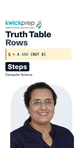 How many rows for two inputs?42 sec
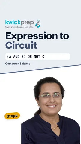 Which part do you draw first?41 sec
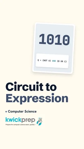 Why keep the brackets?42 sec
The full lesson, in text
Hello students, welcome to Kwickprep. A computer has no brain, only billions of tiny switches. So how does it decide anything? The answer is logic gates. Today we will build AND, OR and NOT gates from switches, fill truth tables row by row, and turn expressions into circuits and back.
First, some new words. A bit is a binary digit, either zero or one, and inside a chip it is a low or a high voltage. A logic gate is a tiny circuit that takes one or more input bits and gives one output bit. We name the inputs A, B and C, and the output is often called Q. A gate has no memory, so the same inputs always give the same output.
Picture a torch bulb with two switches in series, which means one after the other on the same wire. Both switches are off, so no current flows, and the bulb is off. Only B is on, but A still breaks the wire, so the bulb stays off. Only A is on, and now B breaks the wire, so the bulb is still off. Both switches are on, the path is complete, and the bulb glows. So an AND gate gives one only when all its inputs are one. We write Q equals A AND B, or A dot B.
Now place the two switches in parallel, which means side by side on two separate paths to the bulb. Both switches are off, so there is no path, and the bulb is off. Switch B is on, so current flows through B, and the bulb glows. Switch A is on, so current flows through A, and the bulb glows. Both are on, and of course the bulb glows. So an OR gate gives one when at least one input is one. We write Q equals A OR B, or A plus B.
The NOT gate has only one input, and it flips it. A NOT gate is also called an inverter. When A is zero, the output is one. When A is one, the output is zero. Think of a push button that cuts the bulb off while you press it. We write Q equals NOT A, or A with a bar on top.
In a circuit diagram, each gate has its own shape. The AND gate is drawn like the letter D, with a flat back and a round front. The OR gate looks like a curved shield with a pointed front. The NOT gate is a triangle with a small circle at its tip. On screen, a dot means AND, a plus means OR, and a small stroke called prime after A means NOT A.
A truth table shows the output of a circuit for every possible input. Its rows must cover every combination of inputs, with none missing. Each extra input doubles the rows, so one input gives two rows, two inputs give four, and three inputs give eight. To never miss a row, count up in binary: zero zero, zero one, one zero, one one. Then work out the output one row at a time.
Let us build a truth table row by row for Q equals A AND NOT B. Row one: A is zero and B is zero, so NOT B is one, and zero AND one gives zero. Row two: B is one, so NOT B is zero, and Q is zero. Row three: A is one, B is zero, NOT B is one, and one AND one gives one. Row four: NOT B is zero, so Q is zero. A helper column for NOT B makes each row easy and saves marks.
Pause the video and try this one yourself. The expression is Q equals A OR NOT A. What is Q when A is zero? What is Q when A is one? The answer is one both times, because one of the two inputs to the OR is always one.
Now three inputs, so eight rows, and we split them over two slides. In the first four rows A is zero, so A AND B is always zero. Row one: C is zero, so zero OR zero gives zero. Row two: C is one, so Q is one. Row three: C is zero again, so Q is zero. Row four: C is one, so Q is one.
In the last four rows A is one. Row five: B is zero, so A AND B is zero, and C is zero, so Q is zero. Row six: C is one, so Q is one. Row seven: A and B are both one, so Q is one even though C is zero. Row eight: everything is one, so Q is one.
Exams often give an expression and ask you to draw the circuit. Start with the innermost brackets, because they are worked out first. Draw one gate for every operator, including every NOT. Connect the output of each gate as an input to the next gate. The operator worked out last becomes the final gate, and its output is Q.
Let us draw Q equals A AND B, OR NOT C. First, A and B go into an AND gate, because that bracket is worked out first. Next, C goes into a NOT gate on its own. Then both outputs go into one OR gate. The output of that OR gate is Q.
Now the other way: a circuit is given and you must write the expression. Label the output line of every gate, for example P and Q. Start at the inputs on the left and move towards the output. For each gate, write its output in brackets using its inputs. Keep joining these pieces until you reach the final gate and Q.
Here is a circuit described gate by gate. Gate one is a NOT gate with input A, so its output is NOT A. Gate two is an OR gate with inputs B and C, so its output is B OR C. Gate three is an AND gate that takes both outputs, so Q equals NOT A AND, in brackets, B OR C. Always keep the brackets, because without them the meaning changes.
Some exams, such as Cambridge IGCSE, ask you to write expressions using the words AND, OR and NOT. Other boards use dot, plus and a bar, and both mean the same. Read the first line as Q equals NOT A, AND, B OR C. Read the second as Z equals A AND B, OR NOT C.
Let us revise what we learned today. An AND gate gives one only when all inputs are one, like switches in series. An OR gate gives one when any input is one, like switches in parallel. A NOT gate flips its input. A truth table has a row for every input combination, filled one row at a time. To go between a circuit and an expression, work one bracket and one gate at a time.
Courses that teach this
| Course | Unit |
|---|---|
| CBSE Class 11 Computer Science (083) | Computer Systems and Organisation |
| CBSE Class 11 Computer Science Essentials (083) | Computer Systems and Organisation |
| ISC Class 11 Computer Science (868) | Boolean Algebra and Computer Architecture |
| ISC Class 12 Computer Science (868) | Boolean Algebra |
| Cambridge IGCSE Grade 9 Computer Science (0478) | 10. Boolean Logic |
| Cambridge IGCSE Grade 10 Computer Science (0478) | 10. Boolean Logic |
| Edexcel GCSE GCSE Computer Science (1CP2) | Topic 1: Computational thinking |
Voice-over in this lesson is AI-generated. The script is written and checked by Kajal Ma'am. Boards can revise a syllabus mid-year, so confirm anything you plan around against the official board circular. Keep your passwords, OTPs and ID numbers to yourself — we never ask for them. To reach Kajal Ma'am, use the WhatsApp button; sharing your number there is how we call you back.
Free to watch, no sign-up. Live classes with Kajal Ma'am are the paid course; these lessons stay free either way.